Dan's GL1100 alternator installation
Here is how I did it on my
1983 GL1100 Interstate.
( !Update 12/14/16!
) Check out other who've done this at our forum classicgoldwings.com
( !Update 12/13/07!
)
The
installations and modifications involved to perform this alternator
installation as I've shown below are very labor intensive and time consuming.
I had to make up all the parts myself.
!Update!:
I got inspired by LD Hack, a member of goldwingfacts.com and moved
the radiator forward!
Now the stock fan is back and no more pusher fan!
Check it out here
!Another update! J
I had a 4 inch diameter one piece crank pulley made to speed the
alternator up and get rid of the washers as shims.
Many thanks to Joe Wiggins for providing the dimensions, it fit
perfect the first time!
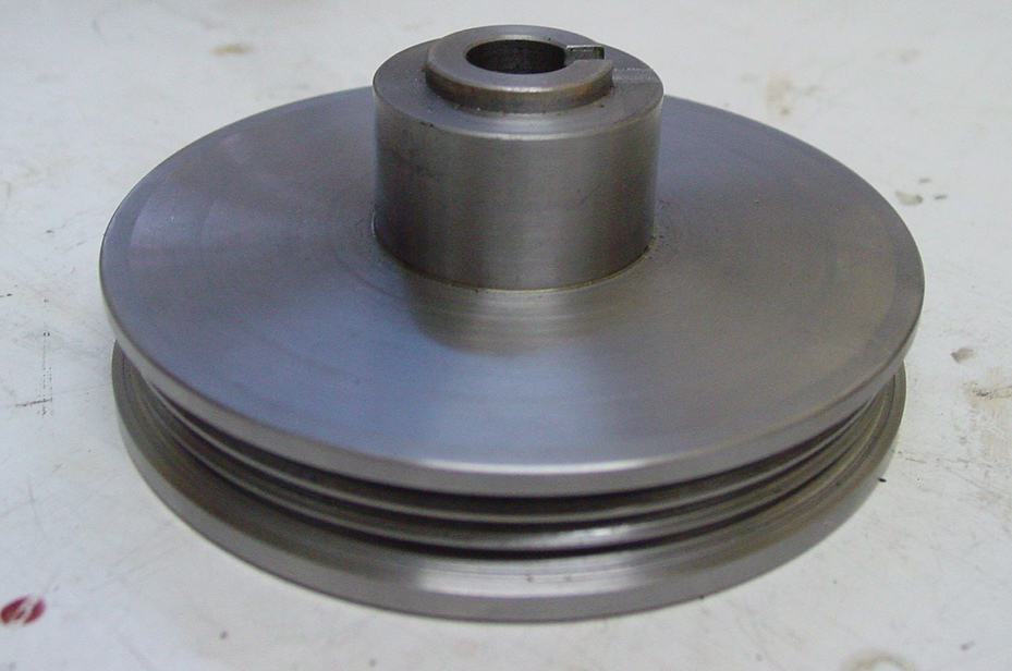
The machinist has all the latest equipment so this pulley is true
and balanced.
Below is a drawing of the pulley.
These are the exact dimensions he used with the exception of the
center to center, belt taper and depth in the cut for the belt grooves, he took
this dimension from the belt I left with him which matched the alternator
pulley:
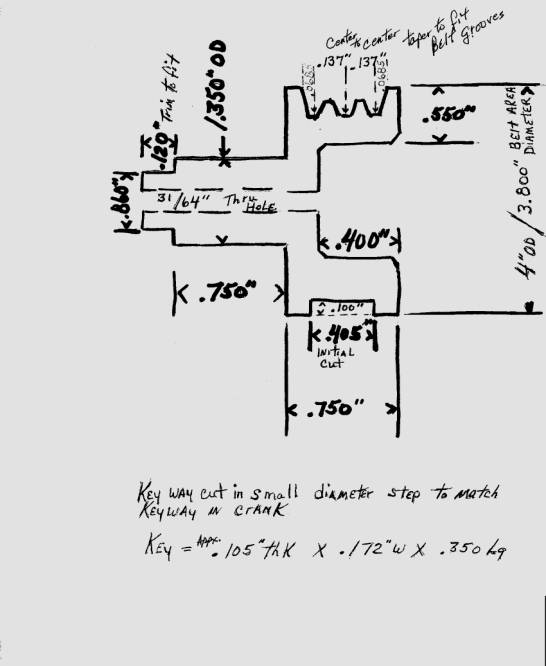
The pulley fits
perfectly on the crank and engages the keyway with a nice snug fit.
Any machinist could
easily modify these specs to accommodate a 5 groove belt or even a V belt
whatever.
I'm trying to
make this a fun project in which other Goldwing owners help each other out and
we do so at our own risk.
Please use any
information, techniques or tricks I have here but also email
me with any ideas you might have or where a certain part might be available
that would work or look better.
The initial build
will be very rough for sure but I'm gonna go back to some parts later and
refine them. Some (or a lot) of machining will have to be done but that's all
part of the fun!
======================================================================================
------------------------------------------------------------------------------------------------------------
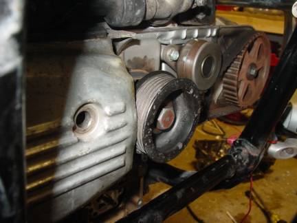
OK, first is the crank pulley.
I'm putting the alternator on
the left side.
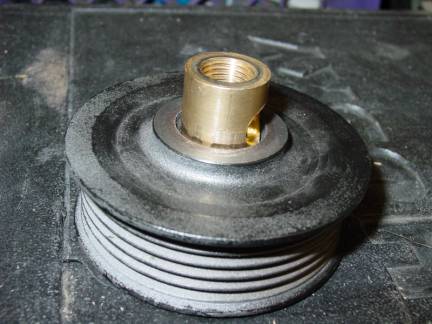
Below is a 3 inch diameter 5 groove alternator pulley which matches the 2 inch pulley on the alternator.
Why a 5 groove?
Mostly because it was what the guy had lying around but also because a 5 groove will grab the pulley better with less slipping.
So I'm told, it looks better too.
Both can be easily obtained
from an alternator shop that's willing to have your business.
The brass sleeve is actually
a light fixture threaded rod coupling. The inside thread is 3/8" which fits the
12 mm crank bolt just perfectly. The outside diameter is 25/32".
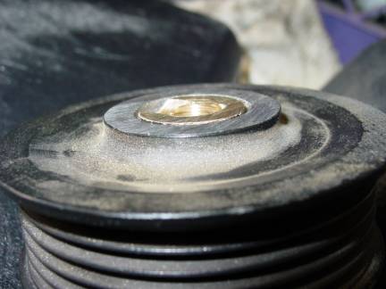
I drilled the 5/8" pulley
hole to 3/4". I drilled to 3/4" rather than 25/32" because the hardware store
didn't have a 25/32" drill bit and I'm getting anxious to get this done
already!
By letting the 3/4" drill bit
wobble slightly in the hole it will easily take the extra little bit off until
it's diameter is very close to the sleeve OD.
Yes I know, sloppy, but it
works.
A 25/32 bit would be better.
A hammer presses it in real
nice.
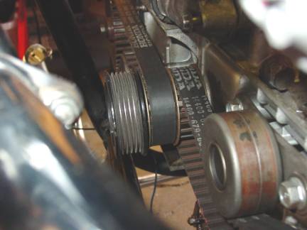
The front side of the pulley
and brass sleeve in the pic below.
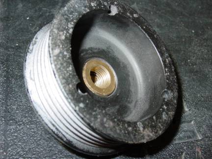
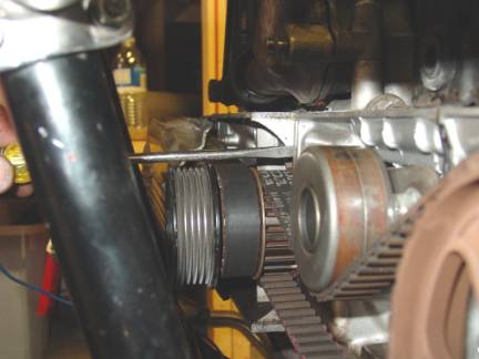
Next I ground the remaining
brass off flush with the rear side of the pulley like in the pic below.
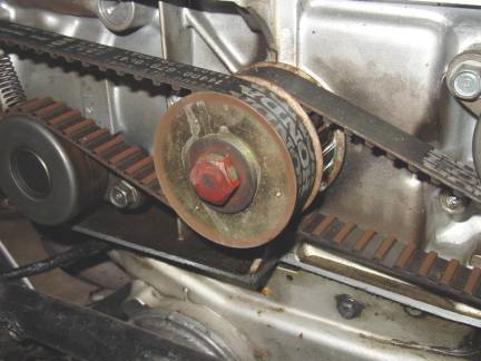
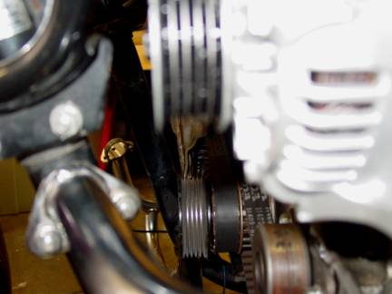
The next pic is the pulley on the crank.
By using a long straight edge
( aka a screwdriver) I cranked the engine to check the pulley alignment on the
crank. It's less than a 16th inch off. I'm hoping this will be ok
and doesn't create some vibration.
I checked the alignment of
the pulley on the alternator and there seems to be at least this much or more
mis-alignment from center.
I'll know once I get the
engine running again.
The pulley alignments are
looking pretty good so far.
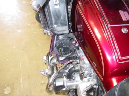
Here's a pic of my rough alternator
mounting.
I say rough but if it proves
strong enough it's staying this way.
I almost went with a L
channel steel like I've seen others do but that just doesn't look to be secure
enough.
I'm after a solid vibration
free installation.
Besides, I want to be
different.
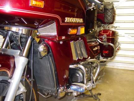
The belt covers have to be
trimmed.
I'm tempted to trim them big
to fit around the pulley but I suppose it's not a good idea to make the hole so
big since water and junk could more easily get inside the cover and damage the
belts.
So my next challenge is to
find a longer crank bolt. For this particular pulley the bolt needs to be 2 1/2
inches long.
I came up with this length
needed by adding the total hub/brass shim length and the additional spacing
that's needed to bring the back side of the pulley pulley out away from the
timing covers, this length is added to the original thread length that screwed
into the crank.
2 1/2" gives me some playing
room so the cover doesn't rub the pulley, or the pulley rub the cover, whichever
way you want to look at it J.
Apparently a 12mm X 1.25
pitch X 60mm long bolt does not exist, at least not where I've looked, but a 50
mm which is about 2" long works fine with enough thread into the crank.
I ground down the "ribs" on
the right cover so I could remove more washers to get more bolt threads into
the crank.
It just clears.
The alternator I went with is
a Nippendenso 60 amp.
I think it comes from a
forklift.
One word. AWESOME!
Very small, about 2/3rds the size of a GM one wire
and the mounts line up nice for bracketing.
Test run with all lights on
and battery at about 75% charged shows 1-2 amps charge and 13.2 volts at 900
rpm.
At 1000 rpm, 15-20 amps and
14.5 volts output.
It then floats right around
there, peaking to about 14.8 volts and 20 amps for a few seconds then backs
down as the battery gets topped off, which doesn't take very long.
The next challenge.
The cooling fan wont fit,
didn't expect that.
The belt hits the fan bracket
to the point that it's time to relocate it.
The original fan is old and
probably gonna die soon anyway so I put a aftermarket fan on the front.
>!Update!<
I advise against
installing the fan this way the fender might hit it during hard fast stops and prevent
the wheel from turning!
At least it did on
mine with this fan, it was too big.

Kinda ugly isn't it.
I have to figure out a way to
dress this up better.
Maybe a chrome fan.
I don't know how others are
making the lower hose connect to the engine but any way I place the original
hose or any aftermarket hose it kinks since the angle is all different now with
the radiator pushed forward to clear the crank pulley.
Time to modify the radiator.
I kinda expected this would
happen.
I used a 3/4" copper EL and
cut the radiator pipe at a 30 degree angle and plenty of solder.
DONE and back on the
road!